Fun with ShoreTel Voice Mail

Stuck on how to get a WAV file of a professionally recorded voice mail greeting into the right ShoreTel Voice Mail box? After all there is no import utility as there is during the creation of an Automated Attendant. I can’t speak for you, but I was curious to know if I could just copy the WAV file to the mailbox? Where was the mailbox anyway? Now that you mention it, where are the voice messages.

ShoreTel has always had a folder entitled “Shoreline data”, the name a residual of the company’s old name, look and feel. Historically, this folder contained all of the information you would need to have available to restore a crashed server from bare metal. The later releases of ShoreTel have moved configuration files to a MySQL database, but you still need to have this folder to do a system restore. The folder, among other items, contains the voice mail structure of your deployment and the actual voice mail files for each individual mailbox.

In the VMS folder, you will find two folders: “Message and ShoreTel”. The Message folder contains actual voice mail messages in ShoreTel WAV format; and the other folder contains a list of folders that match the number of each mailbox on the ShoreTel deployment. Each VM box folder contains a WAV file for the mailbox name and each greeting recorded in that users mailbox. The greetings have easy to recognize names like 115Greet01_01.wav which represents the Standard Call Handling mode Greeting. If you re-record your greeting you will create a new file named 115Greet01_X.wav, where X is the revision number of the recording.

There is a also a Mailbox.DAT file that contains system configuration information and the unique ID of every message received by that particular voice mail box. The actual voice message, however, is contained in a separate folder appropriately named messages! In this file you will find a unique message WAV file that is the actual voice mail recording. It will have the format 1K0VGJSGI.wav where 1K0VGJSGI being unique message identification. There will also me a matching 1K0VGJSGI.msg file that acts as an index pointed to by the unique message identification written to the DAT file in the individual voice mailbox folder.

ShoreTel has a number of debug and diagnostic tools that can be used to assist in administration and troubleshooting. The CFG.exe program is a useful tool for obtaining information about mailboxes, voice mail servers, phonebooks, automated attendant DNIS maps and other specific voice mail box configuration data. Using CFG you can turn on message waiting lamps, have the voice mail system dial specific extensions, list message details, purge and restore messages and generally manipulate the voice message structure. The three part video clip details all of this information for your education and enjoyment!

PDF and Email those ShoreTel Historical Reports!

“Historically”, excuse the pun, we always had a challenge with ShoreTel Contact Center Historical report!There were two issues.First, though you could schedule a report to be run automatically at a present time, you had to chose between printing to a file or printing to an actual print device.If you choose to print to a file, you could not set the path for any location other than that set by the default path of the ShoreTel Contact Center.Secondly, most Supervisors would rather have the scheduled report converted to a PDF and emailed to them!Automating the report is wonderful.Automating the delivery, however, was more important.

In Version 5.1 both of these challenges have been addressed, though a bit of “IT Magic” is still required.ShoreTel provides the path manipulation and email ability, but the GNU project provides the PDF conversion capability.You need to go to http://sourceforge.net/projects/ghostscript and download “ghostscript”. Once you have this software you will use standard Windows facilities to install a new “local” printer to enable the Ghostsciprt PDF printer! This is the first step, printing your Historical reports on a schedule and have them output to a file in the form of a PDF. Works like magic!

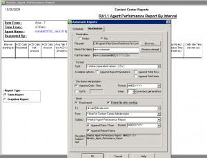
The second part takes advantage of the DESTINATION tab in the ShoreTel SCHEDULE option for Historical reports. After you create your Historical Report Template you then have the option to schedule the printing of the report, to a file or to a printer, To have the report emailed to you, you print the report to a file at a scheduled time. You then indicate that you want the report emailed and you complete a simple form that indicates who to email, who the report is from and what the subject of the report is. At the scheduled time, the report is generated, sent to a file through the Ghostscipt option to obtain a PDF and then the ShoreTel SMTP email option forward the email on to the intended recipient.  In 5.1 it is no longer necessary to separately configure the SMTP options.

Sometimes it is the really simple stuff that makes it a desirable feature. This new ShoreTel Contact Center configuration for Historical reports is among the most frequently requested capabilities we have heard among the installed base of Contact Centers! Kudos to the ShoreTel ECC development team for getting this done! Wonder if this will work on ShoreTel IPBX CDR reports?

emailreports1

ShoreTel PCM 9.1 Microsoft Installation Error

When installing the ShoreTel PCM 9.1 call manager software on a PC that has been upgraded to Windows XP service pack 3, occasionally there is a Microsoft Installer error that prevents the ShoreTel software from being installed. The error is “Error 1720 – A script required for this install to complete could not be run”. The installation will then fail requiring the issue to be corrected and the installer to be ran again. This is caused by an issue with the Window XP service pack 3 install that sometimes will corrupt certain binaries used by the OS. Microsoft recommends a reinstall of the “Microsoft Distributed Transaction Coordinator” to correct the issue. This challenge is usually only noticed in a handful of service pack 3 machines where the corruption is present. http://support.microsoft.com/kb/891801

ECC Medical Applications

With all the talk about “health care” you would expect growing demand for  more application integration for this particular industry vertical!  The ShoreTel Enterprise Contact Center can process “dial lists” that enable the system  to make outbound phone calls.   The “dial list” typically gets a list of phone numbers from a MySQL database that can be populated by some other application, like scheduling software.   It would not be out of the realm of possibility for the ShoreTel ECC to be used to confirm appointments or to generate a broadcast message that could be confirmed by a script that captures DTMF responses, including the ability to talk to a live person!

The ShoreTel Enterprise Contact Center, though primarily and inbound call processing solution, can be applied to do outbound campaign dialing.   In addition to the native SQL scripting tools,  the system  can integrate with a wide variety of applications through either OBDC, XML or “triggers” and we have had experience with each of these options.    There is a young man up in the bay area, Houston Neal,  who has been writing a bit about Health Care Applications and you might take a minute to check out his recent article on this subject:  Seven Great Applications for PBX systems in Medial Practice.

The ShoreTel Prefix Option

In this economy, there are a growing number of mergers and acquisitions, or “marriage by shotgun”. When companies combine they have the challenge of integrating their data and telecommunications systems. For example, we have witnessed an increased demand in companies seeking technical assistance in merging ShoreTel systems. There are two basic options for doing this and the choice often depends on resource requirements and “dial plan” conflicts. To illustrate these options let’s assume Company A merges with Company B. Both companies desire the integration of their telephone systems if for no other reason than to enable the extension to extension dialing.

The first option is the traditional single image option. Assume that Company A will become the HQ Server and the other Company B will become the DVM server. To accomplish this, the database of Company B will be manually imported to the HQ server and a new site is created. ( Clearly, the WAN solution is in place and connectivity between the two companies exists). When you complete the database additions to the HQ server, adding all the new users, switches, workgroups, hunt groups and site details you are ready to convert the Company B HQ server to a DVM. You are going to have to reconfigure the site switches to point to the new Company A HQ server, but the process is manageable and you should achieve the desired result with limited downtime.

The second option is less obvious and many ShoreTel field installation technicians will not be familiar with the option. Out of the box, ShoreTel supports site based Prefix Dialing. In our example, we would leave both Company A and Company B with a HQ server. They would appear to be two separate systems. The use of the Prefix dialing, however, makes it possible to enable the extension to extension dialing between the systems. Through the ShorewareDirector web portal, you would select the Dialing Plan from System Parameters. The dialing plan would enable you to select a digit for extension dialing, with from 1-7 prefix digits. In our small example, we might make use of Digit 7 with a prefix of 2 digits, allowing us to create 99 sites.

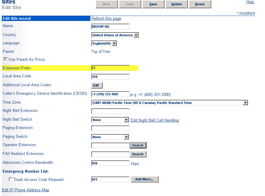
When you exercise this option, you will see a new field appear in the SITES definition in the ShorewareDirector portal. Entitled “Extension Prefix” the field enables you to assign a two-digit SITE ID to each site you create. As you assign users to SITES, their extension numbers become the SITE ID + Extension number. Given that we have a WAN solution in place, we can then establish SIP Tie Trunks between Company A and Company B. The Trunk Group that defines the TIE LINE would have an OPX (off premise extension ) list that defines the extension range that “lives” at the other end of the TIE line. Company A might have a prefix of 77 and Company B might have a prefix of 78. Users in each system, even though they were previously defined with a three digit “dial plan” would now show 77-123 or 78-123 when you reviewed their individual USER configuration in Shoreware Director. Assume further, that both companies had similar “dial plans” meaning that they had the same extensions assigned in both companies! The extension prefix option working as a site ID, enables both companies to keep their extension numbers.  From within your site, you only dial the extension digits.   You dial the prefix digits + extension number to reach someone in a different site.

site-id1

Arguments can be for, or against either option.A single image solution has real advantages in that there is a single point of administration and a single VM system.Others would argue that redundancy and increased resources favor the second option.Remember that currently, ShoreTel “Workgroups” are not a distributed service.The second option enables some workgroup survivability given an HQ server failure. Prefix dialing has a place in the integration of independent systems and can work to reduce HQ server work load while increasing resources and mitigating dial plan conflicts.

More on ShoreTel LLDP – follow up to previous blog post!

This is a follow up post to an earlier post on LLDP-MED. VoIP phones on the market today follow the same basic boot and operations process:

1 – Wait for an LLDP packet from the Ethernet switch

2- Send a DHCP discovery packet to find the DHCP Server

3- Send a DHCP request to the DHCP server to get an IP address

4- Send an LLDP-MED packet to the Ethernet switch

5- Wait for an LLDP-MED packet from the Ethernet switch and read the Network Policy TLV to get the VLAN ID, L2 priority and DSCP value

6 – Download applciations and software from the “call manager”

7 – After configuration , voice packets are sent as tagged frames and data packets are sent as untagged frames

The ShoreTel implementation of LLDP seems to follow this process only after step 5, the result of the IP Phone learning LLDP by having its firmware configured. In other words, a phone out of the box is a hung of iron with no inherent ability to define itself as an IP phone to an LLDP enabled ethernet switch. The ShoreTel phone will still require an intial boot in the native VLAN and then reboot in the voice vlan, where it will then download its firmware. The real value here, is that once this process is “learned” by the ShoreTel phone, should the phone restart for any reason in the future, it can start at step one above. LLDP in ShoreTel is a version 9.1 feature enhancement not available in earlier releases of ShoreTel.

update 2/15 see  article at Support.DrVoIP.com

How to cause a ShoreTel phone to dial from within Outlook

We see a lot of request that can be summarized as   “can we dial from within<(insert your favorite application here>?   Outlook, for example, has an ability to let you select the ShoreTel TAPI line so that you can dial from a Contact.  Here is how you set it up.  First, in the tool bar of the Outlook Contact, you should  see a PHONE ICON.  Selec the Icon to open configuration options:

Outlook Tool BarThe select the “Dialing Options”.  In the new box that opens, you will see a drop down box that allows you to select the ShoreTel  TAPI line with Outlook should use to dial  (this would be the same for any other applicaton that supports TAPI based dialing).

Select TAPI lineIf you see the call is attempted but fails, you may need to check the “Phone and Modem Options” in the Microsoft Control Panel to ensure the system is setup for the appropriate area code and Trunk Access code.

Phone and Modem OptionsOther than that, there are no other settings and the ShoreTel should “smile and dial”!

How to Telnet into a ShoreTel phone

A typical trouble ticket might sound like “when another extension calls me, I can hear them, but they can not hear me”!  Actually, one of my personal faviroites.  Over the years I have come to learn that this is usually the result of one of two issues: someone has the wrong default gateway; or port 5004 is being blocked by some firewall in one direction.  As we move more and more toward SIP and media streams move away from a dedicated port, this issue is almost always a network configuration error.

So which device has the wrong default gateway?   That takes some dedective work.   Generally you will telnet into the ShoreTel SG media gateways and check the configurations.   Media stream between phones generally do not need an SG switch beyound call setup.  The media stream, once the call is setup, is between the two phones.   For this reason, you will want to tenet into the phone and “see” the network from the phone’s percepective!   To do this, you will need to know the ShoreTel methodology and process.

Security on the SG switches and phone, requires that you start the process from the ShoreTel HQ server.   There is a specific subdirectory that you need to be in to launch the various utilities.  This silent viedo walks you through the process of using one utility, phoneCTL, to telenet into a phone and look around.

Switch Connectivity Diagnostic

Most ShoreTel System Administrators learn early on that the “Quick Look” link in the ShoreWare Director is your best friend! After all, telephony trouble indications are easy to spot: Green is good, Red is Bad and yellow means “something needs attention”. At the first report of a trouble indication, a System Administrator will bring up a browser and get to the log in screen of the Shoreware Director portal. Quick Look, Under the Maintenance section of the administrator portal, provides an immediate snapshot of what is going on in the system. If you see any RED at the HQ level, you can drill down and find the site and switch that might be the source of your problem.

What happens when you look and you see Green?All is good!Why am I getting user reports of inability to complete a phone call?The very best next step for you to take is to click on the Switch Connectivity link under the same Maintenance section as Quick Look.The switch connectivity screen will illustrate any connectivity issues between switches on the network. It is very possible that the HQ server “sees” all is well and reports Green, but individual switches served by DVM’s, for example, do not see each other.By pinpointing the intersection of switches that can not communicate with each other, you will generally find a network or default gateway issue that is causing your negative user reports!As useful as the Quick Look may be, the Switch Connectivity page is a more useful diagnostic for locating network based issues.

switch-connectivityFor more detailed information about a switch, place the mouse cursor over the connectivity cell in question and status information will be displayed in the status bar at the bottom of your browser!  Green is Still Good and indicates the Switch is communicating with the other switches in the system.  Yesllo indicates that the switch connectivity is unknown because it can not communicate with TMS and RED indicates a complete loss of communications with the server!

The missing ShoreTel Beep!

In both ShoreTel Release 8 and 9 there is a very interesting behavior that will ultimately bring a client call to your support center.   The behavior is most obvious in a multi-site deployment in which there is only one HQ server providing voice mail services.    A call to a user at a remote site is RNA (i.e. ring no answer) transferred to the voice mail system.   The call entered the system on a PRI at the remote site and is then transferred across an MPLS WAN to the HQ server.   The caller hears the greeting: “I am not here, at the beep please leave a message”.   The caller dutifully waits for the “beep”, but it never comes.  What happens to it?

The fact of the matter is the “beep” was in fact played, but the caller did not hear it.   This has to do with the use of the G729 Codec on Inter site calls in this scenario.   The G729 is distorted to the point that the caller can not hear the beep.   The distortion appears to only be related to the implementation of the G.729 codec on the virtual soft switch.  As a troubleshooting step, I used a different phone system and an IP phone that was set to only use G.729.  When we called the HQ virtual soft switch over a local PRI trunk where ULAW was being used from the PRI switch to the HQ server, we heard the voicemail beep without distortion (through the G.729 codec as implemented on a different PBX).  It is only distorted when the virtual soft switch is trying to do G.729.

Outlined below are two WAV files of the normal beep (ULAW) and the distorted beep (Softswitch G.729).  We have also attached a visual representation of the audio files.  The distortion is audibly and visibly clear.  Our thinking is the “beep” is to short and to high a frequency, but we are not developers!  Currently, the only known fix for this is to change the Codec to G711.  That fixes the issue, but it may have a negative impact on your WAN plan!  I am sure there is a fix in the works back at the ShoreTel Mother ship, but we have not seen it yet.

waveforms