ShoreTel Enterprise Contact Center “Change Call Profile” icon

How many people hit the Auto Attendant and then dialed one for Sales? One of the most requested reports from ShoreTel clients is the analysis of Automated Attendant key strokes. With in the ShoreTel iPBX there are probably several ways to implement this, but we prefer the use of “route points” (see past blog). “ Thank you for calling our company during our normal business hours. For Sales Press 1, for Service Press 2 or stay on the line and the next available member of our staff will be right with you”. Typical Automated Attendant? We set the time out value to go to a “hunt group” and each of the menu items to a route point. You can actually run a User Detail report against a route point, as long as that route point terminates on a Shoretel end point other than a TAPI end point. For this reason, you can then run the report and find out exactly how many callers dialed one for sales!

Recently, we had to create an Automated Attendant on an Enterprise Contact Center. At first this seemed almost boring, but then we ran into an issue. You can use the MENU icon to create your Automated Attendant script, with a TRANFER icon to each destination selected by the caller. You can use the SCRIP icon to send the caller on to a script to collect information like the callers account number for a SQL database look up; but how do you send a caller to “service”? Now that was a more interesting challenge and I have to thank Chad Burnett for pointing out the use of what has become my favorite new ShoreTel ECC scripting icon: “the Change Profile” action. This icon is a powerful call profile manipulator and enables the Enterprise Contact Center configuration to explode with call processing options.

Using the Change Call Profile icon you can select various Call Profiles for manipulation. Each system contains a number of mandatory system level call profiles like ANI and Caller ID. You as a system designer can also create Call Profiles to meet the needs of your exacting design requirements. For example, you might add the Call Profile “Account Code” that you might use in a script that prompts the caller to enter digits that you will use to look up a record in a SQL database.

The Change Call Profile icon also allows you to select a previously defined SERVICE. The following video clip reviews how the iPBX and the ShoreTel ECC interconnect. It demonstrates the use of the Change Call Profile icon, by demonstrating the creation of a simple automated attendant!

SIP firmware for ShoreTel handsets?

To the sales team, I sound like a broken record as I repeated the engineering driven mantra: “A VoIP solution is only as good as the network it is build on”.     No matter how many times we tell clients that you can not obtain reliable, predictable toll quality voice communications over the public Internet, they insist on having us implement it.   The old marketing adage “you do not give customers what they need, you give them what they want” clearly applies and despite our best arguments to do otherwise; we find ourselves implementing VoIP solutions using VPN over DSL or Cable.   The good news is that when it works,  it is  often useable for inter-office communications.   When it does not work, it sounds like the worst cell phone  call and would not be something that you would use to support business communications with a client.

In the VoIP world in general and the ShoreTel world in particular, there is a measurable performance difference between an MPLS deployment and a VPN tunnel through the public internet.    An appropriately designed MPLS circuit with carrier Service Level Agreements in place will out perform the best VPN tunnel through the public internet.   Yet clients continue to believe they can put a VoIP handset  at the bosses house and run it over a DSL based VPN back to the “puzzle palace” and that it will  perform as well as the phone on his office desk.   The reality of the deployment is that this implementation seldom meets customer expectations.

A ShoreTel deployment of a remote handset for a home based work force can be accomplished under two basic models.   In the more desirable, albeit more costly model,  we create a “site” which involves the placement of a ShoreTel media gateway (read SG switch) at the remote location.  VoIP handsets interact with the SG media gateway or call manager at the remote location for all call setup, addressing, signaling and control.    In the ShoreTel world the call setup between a VoIP handset and an SG media gateway will use the MGCP protocol.   This protocol is a client/server or master/slave model and when compared with other protocols can generally be summarized as complex and “chatty”.   ShoreTel implements SIP for SG-SG communication, but uses MGCP for SG witch to handset call control.  Once a phone call is setup up, only the RTP media stream needs to traverse the VPN tunnel, however.

The other less expensive model s the placement of a remote VoIP handset only.   In this model, the handset is part of the “headquarters” site.  Unfortunately this is the deployment model we see the most when clients attempt to interconnect a single home worker with the corporate network with out the benefit of a carrier SLA.     A DSL, hopefully with a static IP address, and a device that can support a “point-to-point” VPN tunnel are the “minimum daily adult” requirement for VoIP connectivity.   In this model, the VoIP handset is communicating MGCP over the VPN tunnel with a call manager at the headquarters location.  Every handset action, from off-hook to digit key depress, is communicated over the VPN tunnel back to a media gateway at the home office.  Very “chatty”.

As engineers we can talk ourselves into a coma when discussing QOS options, DSCP markings, router queuing strategies and bandwidth reservation parameters.   At the end of the day, however, the only QOS “opinion” that really matters is what the users thinks!   Mean Opinion Score or MOS is the measure of what users rate the quality of a phone call.   Here is what we have learned after supporting hundreds of remote users on none SLA based circuits, typically VPN over DSL and Cable.   Rule one:  use only symetrical circuits (same up and down load speeds).  Rule two: Hard phones beat soft phones; and Rule three:  SIP phones beat MGCP phones.  It is that simple.   If we put a SIP based phone at a remote location, they will out perform an MGCP based handsets on the same circuit as measured by user MOS!  The SIP phone will perform with a higher level of reliability, be more resilient to latency and jitter, and will experience significantly less call disconnects than an MGCP based VoIP handset.

If you study the hosted VoIP service provider market, you will find that the predominant VoIP handset deployment strategy is SIP based.   Why is that?  We could go completely geek on you and  illustrate the complexity of call setup comparing MGCP with SIP setup messages, but why bother.  MOS rocks.  In this environment SIP deployments will yield higher customer satisfaction scores than MGCP deployments.   We are sincerely hoping and praying that ShoreTel has a “SIP firmware load” on the product road map to support their family of outstanding desktop handsets as they do not have a SIP handset solution.    Currently, when we have to support remote workers who insist on running VPN tunnels over DSL and Cable, we deploy Polycom and Aastra handsets to achieve maximum customer satisfaction in the wild west of internet telephony and home based workers!

Fun with ShoreTel Voice Mail

Stuck on how to get a WAV file of a professionally recorded voice mail greeting into the right ShoreTel Voice Mail box? After all there is no import utility as there is during the creation of an Automated Attendant. I can’t speak for you, but I was curious to know if I could just copy the WAV file to the mailbox? Where was the mailbox anyway? Now that you mention it, where are the voice messages.

ShoreTel has always had a folder entitled “Shoreline data”, the name a residual of the company’s old name, look and feel. Historically, this folder contained all of the information you would need to have available to restore a crashed server from bare metal. The later releases of ShoreTel have moved configuration files to a MySQL database, but you still need to have this folder to do a system restore. The folder, among other items, contains the voice mail structure of your deployment and the actual voice mail files for each individual mailbox.

In the VMS folder, you will find two folders: “Message and ShoreTel”. The Message folder contains actual voice mail messages in ShoreTel WAV format; and the other folder contains a list of folders that match the number of each mailbox on the ShoreTel deployment. Each VM box folder contains a WAV file for the mailbox name and each greeting recorded in that users mailbox. The greetings have easy to recognize names like 115Greet01_01.wav which represents the Standard Call Handling mode Greeting. If you re-record your greeting you will create a new file named 115Greet01_X.wav, where X is the revision number of the recording.

There is a also a Mailbox.DAT file that contains system configuration information and the unique ID of every message received by that particular voice mail box. The actual voice message, however, is contained in a separate folder appropriately named messages! In this file you will find a unique message WAV file that is the actual voice mail recording. It will have the format 1K0VGJSGI.wav where 1K0VGJSGI being unique message identification. There will also me a matching 1K0VGJSGI.msg file that acts as an index pointed to by the unique message identification written to the DAT file in the individual voice mailbox folder.

ShoreTel has a number of debug and diagnostic tools that can be used to assist in administration and troubleshooting. The CFG.exe program is a useful tool for obtaining information about mailboxes, voice mail servers, phonebooks, automated attendant DNIS maps and other specific voice mail box configuration data. Using CFG you can turn on message waiting lamps, have the voice mail system dial specific extensions, list message details, purge and restore messages and generally manipulate the voice message structure. The three part video clip details all of this information for your education and enjoyment!

Trouble Shooting ShoreTel SGT1 Caller ID

Caller ID is an interesting area and we see a variety of client request regarding this functionality. On analog lines, there is not much room for configuration. Generally this information is transmitted as FSK (i.e. modem tones) in either the SDMF or MDMF format, in the silent portion of the phone company “ring cycle”. For this reason, if you answer an incoming call before the ShoreTel has an opportunity to capture the CID information, you may not see it displayed. Unlike a PRI, outbound caller ID is controlled entirely by the phone company on analog lines and ShoreTel can do nothing to change what is displayed when you call out of the system. Sometimes, if you have a number of analog lines, the phone company displays a different Caller ID on each line! If you ask nicely, and the moon and starts are in perfect alignment with Mars, the carrier might agree to have all of your analog lines display the main Billing Telephone Number or BTN of the client account. At the end of the day, outbound caller id, is what it is on analog lines.

On PRI lines, we have more control over what is displayed when you place a call to an outside party. Generally, in ShoreTel you can display either the main PRI number of your personal DID number. We have been able to spoof the PRI D channel and display any phone number you may want on an outbound call, by configuration of the Caller ID field in the Shoreware Director administration portal under Individual Users.

We are often asked if it is possible to display a different outbound caller ID on a call per call basis. Unfortunately, unless you are willing to reconfigure the Caller ID field this is difficult, but not impossible to do. ( I know at least one police department and a half dozen credit and collection agencies that do this when the called on suspects might not answer the phone unless they know that Mom is calling)! Sometimes a company has multiple Brand names or company names that they are using when they place phone calls. To enable call by call, outbound CID change, we create Bridged Line Appearances or BLA’s. These BLA’s can be configured with a different called ID and the client can select the appropriate line (read Brand) to generate the correct CID on a particular outbound call. As an aside, we note that the carriers are getting more particular about D channel spoofing of CID on PRI calls. On SIP trunks it is all but impossible. The Carriers now insist that the displayed number must be a number that is within your BTN range. This limits spoofing.

Trouble shooting inbound (or outbound, for that matter) Caller ID calls on a ShoreTel PRI is fairly straight forward. Minimally, you can use the Trunk Test tool to witness the caller ID of an inbound call. To tap the actual D channel messages sent by the carrier to your ShoreTel SGT1, you will need to setup a capture. To do this, you will need to take the following steps (see video below):

(a) Turn off the Telnet Security Shell via the ipbxctl command

(b) Telenet into the ShoreTel SGT1 switch;

(c) For Analog & T1 turn on the mpm_debug_mask=-1 command

(d) For PRI use mpm_debug_mask=0X40 for called ID and Name.

Unlike the early versions of ShoreTel debug routines, the CID and call setup information is reasonably intuitive to decipher. Traces can also be used to figure out who hung up on who and other carrier CPE shoot out questions. These are useful trouble shooting tools.

Lastly, we need to make sure we understand the difference between ANI (automatic number identification) and Caller ID. ANIS is tariff differently and is not subject to the same blocking restrictions as caller ID number. Generally, if you are paying for “toll free” numbers, you want to know who is calling! The carrier delivers the information in a format that looks like <DID> <DNIS> * <ANI> * <DID/DNIS> and the SGT1 can note the *delimiter and sort this out. You should also be aware that ShoreTel will attempt to route the call based on a selection priority that starts with DNIS, DID, Extension and finally Tandem Trouncing. If no match is found, the inbound call will be routed to the “destinations” specified for the trunk group, with the automated attendant being the default.

ShoreTel Route Point Configuration

Thecr ShoreTel IPBX “Route Points” are powerful configuration tools, generally used to enable third party applications.  Using route points, an external application can gain complete call control.  For example, when you configure a ShoreTel Enterprise Contact Center, you will use route points to control call flow, media and routing options.  The interaction with the route point is generally through TAPI and TAPI wave, but route points can be used to create other options for call control including call deflection and the creation of voice message repositories.

Playing with route points is an interesting experience as they seem to work differently depending on which version of ShoreTel you are running.   In all versions, however you can create a route point and associate it with a voice mail box, or use it to deflect a call.   Historically, we have used route points, along with schedules, to redirect call center traffic between different call centers based on the time of day or day of week.

It is quite possible, however to set up a route point for no other purpose than to create a fully functional voice mailbox.  Given that the route point does not require the definition of a user, no extension or mailbox license is required to achieve this result.   Basically, you create an route point much the way you would create a Hunt Group, Automated Attendant or Workgroup.   You define the route point with an extension that can be dialed, and you setup your Ring No Answer and Busy Destinations to be the voice mail port.

We have come to realize that you have to use the Record function on the Route Point configuration page to set the recorded name and greeting. Thought we could enter the same VM box through an IP phone and were greeted with the normal new voice mail box setup routine, when we called the box we did not hear the name or greeting. Using the record option on the configuration page, however, enabled this functionality. After recording the greeting and name in the way, we experienced the expected behavior when we called the extension and were transferred to VM.

Route points can also be used to deflect an incoming telephone call to an external telephone number. This is equivalent to setting your call handling mode to always call forward to an external number. We never encourage users to configure this option in their call manager, as it robs the host company of follow on call control, allowing messages to be taken by a cell phone for example. The fact remains, however, that you can setup a route point, with a DNIS or DID number to always send the call to a remote phone in the pubic switched telephone network.

Route points that forward to traditional TDM connections will actually show up in the ShoreTel CDR when you run a User Detail or Summary Report. This is not the case if you try to run these reports against a route point that is actually used as designed and terminates in a third party call control application via TAPI. This is just one of the mysteries of route points. At the end of the day you could setup a ShoreTel server with no users or extensions, using route points to enable both voice mail and remote call forwarding. Route points are just way kool and worthy play things! More on this later, film at 11.

To VLAN or not to VLAN, that is the question!

An assumption in this blog  is that if your company has a  “network administrator”  on staff, you have a network that is large enough to require constant  “care and feeding”.    As such dumping a bunch of VoIP phones onto your network without VLAN’s  would never happen.  After all,  the fist job of a network administrator is to make the network broadcast space smaller and smaller.  That is why we subnet!   Take a typical Class C network with 100 network devices on it and dump another 100 VoIP phones in that subnet and you are asking for trouble if you don’t VLAN.   To suggest you don’t need a VLAN or at the very least,  a  separate subnet is just plain silly.

Did you ever hear the expression ‘fences make good neighbors”?     Well the same concept applies to networks and VLANs make network applications like voice and data, excellent neighbors!   Lets assume those 100 desktop computers are in the 192.168.1.0 /24 subnet and you created a new 192.168.2.0 /24 network for your VoIP phones.   In a ShoreTel deployment, you will have personal call managers installed on the computers in one network that need to get to the ShoreTel server and switches  in the other network.   How are you planning to do this?    Use the old “router on a stick” solution (send all my LAN traffic up one switch port to a router and back down again)?   Let me help you here, no!   You are going to set up VLANs  and do inter-VLAN routing at backplane hardware speeds  on that new POE Ethernet switch you purchased to support your VoIP deployment.

Data networks have become “mission critical” for even the smallest of companies today.   Just unplug someone’s Internet connection and you will quickly find out just how important the “network”  has become!    Start bogging down the network with Voice, Video and Streaming audio and you will quickly learn the value of VLANs.   We invest billions of IT dollars on firewalls, spam ware and website filtering software so why would anyone suggest that a VLAN is just to complex to bother with?   By the same (excuse the pun) token, why would someone suggest buying a new POE Ethernet switch that was not VLAN capable?

Data networks need to be described within the context of the protocols and business applications that are running on them.   Big or small, we continually find that VLANs are an essential component in the maintenance of proper network hygiene.    Imagine even a small VoIP deployment in a company enraged in video animation and you can quickly realize that it is not only how many devices I have on the network, but how my network is being used that will determine the qualify of voice in this deployment.    We need to make sure that streaming video over even our LAN, does not negatively impact our VoIP deployment.   To do this, we need prioritize voice over data and that means we have to establish QOS.   To enable LAN based QOS you have to VLAN, because the class of service markings live in the VLAN tag!

Put your VoIP deployment in a multi-site environment with WAN links and the VLAN discussion now moves into the realm of “must have”.     Routers use the TOS byte in the IP header to provide enable QOS.   As an aside,  ShoreTel had the advantage of enabling Transport layer QOS  as the VoIP media stream as always on port 5004.  With the move to SIP, this advantage has been minimized as the media stream now moves unpredictably over some 16K ports. We can pass QOS information to our WAN links through a variety of strategies, but VLAN’s are an essential element of that strategy.

At the end of the day, unless you have a network that is so small you are running Vonage as your VoIP solution, you need to VLAN! Make sure that your VoIP deployment includes an assessment of your network and that you graphically understand how the network is utilized before you deploy voice. As your internetwork becomes more essential to your network, VLANs will surface into high relief on your radar screen. Consider that your shiny new ShoreTel now provides for Internet messaging and desktop Video as part of its advanced feature set, the idea of deploying a solution without a VLAN is just plain silly.

How to create ShoreTel AA and ECC audio Files!

You can hardly install a Automated Attendant with out creating the Audio files!    If you have looked at any of our videos on setting up the ShoreTel Enterprise Contact Center, you know that we urge you to create all of your audio files before you start setting up your Contact Center Services!   Making recordings should be easy enough, but ShoreTel wants to have the wav file in a specific format:  CCITT-mulaw, 8Khz, 8bit Mono.  This is easy enough to create with something as simple as the standard Microsoft Sound Recorder, but the default wav format is some other format  and you will need to “save as” clicking on the format change option!

There are actually three other strategies for recording voice prompts in the native ShoreTel format.   Early versions of ShoreTel provided for a “preference” extension, used by the System administrator to indicate which phone would be used for making recordings.  The System Administrator would set a specific phone phone for this purpose and when you pressed the Record button from within the Automated Attendant screen of the Shoreware Director, that phone would ring and you would then make your recording.

The resulting wav file would be stored in the Shoreline Data folder, in the prompts sub folder and it would be in the correct ShoreTel format.   With Version 7 of ShoreTel, the option existed to enable Automated Attendant recordings by logging into the voice mail system, using the Automated Attendant greeting number as the voice mail extension number.   This was an exciting possibility as it allowed recordings to be made remotely and on the fly as required to meet specific emergency or holiday requirements.

Unfortunately, the files that resulted from these two recording techniques had very unfriendly file names.   When managing greetings through the automated attendant, it would be nice to have a wav file with a name that related to the greeting.    As a result the best practice method of enabling ShoreTel recordings is to use your Personal Call Manager!   By creating a recording using your Call Manager, you are able to name the wav file something useful and you are able to export the recording as in the appropriate format.

Over 15K ShoreTel desktops later, people are still asking me how to make an automated attendant recording!   I though I would generate a short tech tip video and demonstrate all three of these techniques!  Enjoy!

More on ShoreTel V switches!

When installing a Shoregear switch, one of the parameters that you enable is to indicate which server is to manage this switch!    Normally this is no big deal, but with the V switch, you need to pay attention to this parameter as it will impact your Automated Attendant and Hunt Groups.

Let us assume we have a V switch installed in Dallas, Texas which is in the CST zone.    If this switch is managed by a server in the PST zone, then we need to adjust the schedules.    When using a V switch in another time zone, which would normally not be managed by a local DVM,  the site will need separate schedules applied to hunt groups and auto attendants.   The hunt group schedule will need time expressed in the time zone of the HQ server (example: site is in CST but HQ is in PST, 8-5 CST would then be entered as 6-3 PST on the schedule for hunt groups).   The auto attendant schedule will use the time zone of the application server (the local V switch) so the time can be entered in the local time zone.

The first time you set this up it will undoubtedly bite you!  So be aware of this configuration issue and save yourself a service call from the impacted User Group!

ShoreTel Contact Center Overflow Concepts and Direct Calls to Agent!

I would like to kill call center challenges with one blog!   In many call center environments, it is possible that an agent has a Direct in Dial (e.g. DID) number that a client might call and bypass the entire call center process!   For a call center manager, this is very frustrating!  You create a Contact Center to organize the flow of calls to your Technical Assistance Center, and clients by pass the process by calling your Agents/technicians directly!

Clearly, you can eliminate this by not giving DID numbers to Agents, but we end up doing this to facilitate an orderly problem resolution strategy.  You might give a client a “homework” assignment and ask them to call you back.   They might object to being put at the back of the queue again, so you give them a DID number that gets them directly back to you.  The challenge is, that this call would not be accounted for in your contact center reporting!   So how then do you provide this feature and also create a mechanism for enabling your contact center to capture all calls for Agent Performance reporting?  One answer is to establish a “service” that has only one Agent in it!   Then build out a DNIS/DID route point to IRN relationship that brings that DID number into the call center and routes it to the Agent.

Actually, it is not a bad strategy!   The Contact Center can now account for all calls, even the ones that reach your Agent through a DID number and you can apply normal Contact Center routing tools like “overflow”, which brings me to my second point!   Is it possible to overflow calls to more than one other group?  Based on more than one overflow time in queue?

The Contact Center provides a wide variety of methods for handling callers in queue awaiting service.   One of the more interesting concepts is the ability to “overflow” a caller from one group to another group based on the amount of time they have been waiting in queue.   This contact center parameter is set within the “service” and can be found in within the tab labeled “Overflow”.

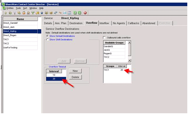
In figure One below, you can clearly see that we have a number of services defined, including a service named TAC1.   Let us assume that this is a technical service group and that TAC1 is comprised of Agents/technicians that include Agent Gandalf, Kipling, Regan and Jack.      You can also see that a service has been enabled by the name “Direct Kipling”.    This service was created to enable callers to Kipling’s DID number to be brought into the Contact Center, and routed to Kipling even though they did not enter through the TAC1 service.   Hopefully, we can now count the phone calls Agent Kipling is handling that otherwise would not be reportable!

ecc_figure_1

In Figure One we can also see that we have set an “Overflow” counter that,  should anyone be in the Kipling Queue for 10 seconds they will overflow to the TAC1 queue.  What is interesting is that when you overflow in the ShoreTel Contact Center,  you don’t leave the queue you are in, you basically add another queue containing agents that have a cumulative effect on the call.    Should that “overflow” not result in an available agent and the caller continues to wait for service, you can actually set a second timer that would “overflow” (e.g. expand the number of agents ) to yet another queue.

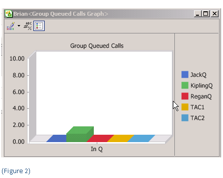
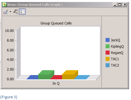
In Figure two, you can see the original call in the Queue for Kipling.  After the pre-configured overflow interval is met, the call is distributed to the “overflow” queue but is also available to the original queue.  You can see this in Figure Three, by noting that the call is now in queue in both the Kipling and TAC1 queue.   In this way, if an agent becomes available, in either the original queue or the “overflow” queue, the call will be answered.   Had we set up a second interval timer in the Service, we could expand the number of Agents to include the additional group specified by that timer.  This is one of the more interesting, if not misunderstood capabilities of the ShoreTel “overflow” concept!

ecc-figure-21ecc_figure-31

More on ShoreTel LLDP – follow up to previous blog post!

This is a follow up post to an earlier post on LLDP-MED. VoIP phones on the market today follow the same basic boot and operations process:

1 – Wait for an LLDP packet from the Ethernet switch

2- Send a DHCP discovery packet to find the DHCP Server

3- Send a DHCP request to the DHCP server to get an IP address

4- Send an LLDP-MED packet to the Ethernet switch

5- Wait for an LLDP-MED packet from the Ethernet switch and read the Network Policy TLV to get the VLAN ID, L2 priority and DSCP value

6 – Download applciations and software from the “call manager”

7 – After configuration , voice packets are sent as tagged frames and data packets are sent as untagged frames

The ShoreTel implementation of LLDP seems to follow this process only after step 5, the result of the IP Phone learning LLDP by having its firmware configured. In other words, a phone out of the box is a hung of iron with no inherent ability to define itself as an IP phone to an LLDP enabled ethernet switch. The ShoreTel phone will still require an intial boot in the native VLAN and then reboot in the voice vlan, where it will then download its firmware. The real value here, is that once this process is “learned” by the ShoreTel phone, should the phone restart for any reason in the future, it can start at step one above. LLDP in ShoreTel is a version 9.1 feature enhancement not available in earlier releases of ShoreTel.

update 2/15 see  article at Support.DrVoIP.com