ShoreTel Route Point Configuration

Thecr ShoreTel IPBX “Route Points” are powerful configuration tools, generally used to enable third party applications.  Using route points, an external application can gain complete call control.  For example, when you configure a ShoreTel Enterprise Contact Center, you will use route points to control call flow, media and routing options.  The interaction with the route point is generally through TAPI and TAPI wave, but route points can be used to create other options for call control including call deflection and the creation of voice message repositories.

Playing with route points is an interesting experience as they seem to work differently depending on which version of ShoreTel you are running.   In all versions, however you can create a route point and associate it with a voice mail box, or use it to deflect a call.   Historically, we have used route points, along with schedules, to redirect call center traffic between different call centers based on the time of day or day of week.

It is quite possible, however to set up a route point for no other purpose than to create a fully functional voice mailbox.  Given that the route point does not require the definition of a user, no extension or mailbox license is required to achieve this result.   Basically, you create an route point much the way you would create a Hunt Group, Automated Attendant or Workgroup.   You define the route point with an extension that can be dialed, and you setup your Ring No Answer and Busy Destinations to be the voice mail port.

We have come to realize that you have to use the Record function on the Route Point configuration page to set the recorded name and greeting. Thought we could enter the same VM box through an IP phone and were greeted with the normal new voice mail box setup routine, when we called the box we did not hear the name or greeting. Using the record option on the configuration page, however, enabled this functionality. After recording the greeting and name in the way, we experienced the expected behavior when we called the extension and were transferred to VM.

Route points can also be used to deflect an incoming telephone call to an external telephone number. This is equivalent to setting your call handling mode to always call forward to an external number. We never encourage users to configure this option in their call manager, as it robs the host company of follow on call control, allowing messages to be taken by a cell phone for example. The fact remains, however, that you can setup a route point, with a DNIS or DID number to always send the call to a remote phone in the pubic switched telephone network.

Route points that forward to traditional TDM connections will actually show up in the ShoreTel CDR when you run a User Detail or Summary Report. This is not the case if you try to run these reports against a route point that is actually used as designed and terminates in a third party call control application via TAPI. This is just one of the mysteries of route points. At the end of the day you could setup a ShoreTel server with no users or extensions, using route points to enable both voice mail and remote call forwarding. Route points are just way kool and worthy play things! More on this later, film at 11.
The ShoreTel Workgroup Monitor Kicks Butt!

As you can tell from our video library and blogs, we are very excited supporters of the ShoreTel Contact Center!  You can not find a more feature rich or cost effective  solution to call routing, email routing  and web collaboration!    To be fair, however,  ShoreTel has always been ahead of the curve with “call center” like  functionality.    Out of the box, the ShoreTel IPBX has an amazing set of features that can fit just perfectly in the small “call center” model.   It may be easy to define the difference between a “call center” (i.e. phone calls only) and a “contact center” (i.e. voice, email and chat); but it is much harder to differentiate a “workgroup” from a true “call center.     ShoreTel clearly believes there is a definable difference and for that reason has always had an impressive call routing option humbly named the “Workgroup”.    Not the “call center” but the “Workgroup”!   Going way beyond simple  “station hunting”, the ShoreTel “Workgroup” enable scall queuing,  Agent  “log in” / “log out” ,  “wrap codes” and provides a rich set of easy to generate performance reports.

ShoreTel has  recently introduced the “ShoreWare Workgroup Monitor”.   This amazing  software package provides real-time, color-coded, graphical views of the the Workgroup and is an optional feature to the already powerful ShoreTel Workgroup feature set.   Compatible with Version 7.5 and up, this software enhancement enables call center management to both optimize and monitor call center performance.

There are three software components:  an application that is loaded into the Shoreware Director or any of the distributed voice servers;  a client application that is loaded on the Supervisors desktop and any version of the ShoreTel Call Manager.    Key  features of this optional software package enable a Workgroup Supervisor to create a standard workspace display or “canvas”.    This “canvas” could be displayed at the desktop or on a “wall board” and provides many of the real time characteristics of a full blown Call Center solution.   With this software you now have the ability to set color coded threshold displays and audible alerts.    We are particularly excited about the ability not only to see abandonded calls, but to click-to-callback!  (Now admit it! How kool is that)?

Supervisors can drill down on the Workgroup of interest, with an easy <> window arrangement.   You can set the threshold alerts for the selected Workgroup to enable Yellow or Red alerts for Calls in Queue, Maximum Wait time and Average Wait time.   The “at a glance”  window gives you a snap shoot of each Workgroup,  indicating the number of calls with longest and average call holding times.   How about a “trend” analysis?  Yup, we got that!   For those spacial database managers with holistic mind sets, you can replace the rows of linear figures with a color pie chart to see Agent status!

The ShoreTel Workgroup feature set,  built on the f the standard out of the box  ShoreTel IPBX,  when combined with the ShoreTel Workgroup Monitor software option is a powerful call center strategy.    It truly rivals any solution in the market at any price point.     (Full Disclosure: ShoreTel does not pay me a dime to write this blog and ShoreTel does not support this site in any way.    I really do believe this stuff).   Keep in mind, we are talking about a single server solution,  not multiple application servers and five acts of  vaudeville to get this call center functionality.  Just  ShoreTel.  Just simple.

Send me a note  (DrVoIP@DrVoIP.com)  and we will get you set up with a free 30 day trail of the Shoreware  Workgroup Monitor!

ShoreTel Contact Center Overflow Concepts and Direct Calls to Agent!

I would like to kill call center challenges with one blog!   In many call center environments, it is possible that an agent has a Direct in Dial (e.g. DID) number that a client might call and bypass the entire call center process!   For a call center manager, this is very frustrating!  You create a Contact Center to organize the flow of calls to your Technical Assistance Center, and clients by pass the process by calling your Agents/technicians directly!

Clearly, you can eliminate this by not giving DID numbers to Agents, but we end up doing this to facilitate an orderly problem resolution strategy.  You might give a client a “homework” assignment and ask them to call you back.   They might object to being put at the back of the queue again, so you give them a DID number that gets them directly back to you.  The challenge is, that this call would not be accounted for in your contact center reporting!   So how then do you provide this feature and also create a mechanism for enabling your contact center to capture all calls for Agent Performance reporting?  One answer is to establish a “service” that has only one Agent in it!   Then build out a DNIS/DID route point to IRN relationship that brings that DID number into the call center and routes it to the Agent.

Actually, it is not a bad strategy!   The Contact Center can now account for all calls, even the ones that reach your Agent through a DID number and you can apply normal Contact Center routing tools like “overflow”, which brings me to my second point!   Is it possible to overflow calls to more than one other group?  Based on more than one overflow time in queue?

The Contact Center provides a wide variety of methods for handling callers in queue awaiting service.   One of the more interesting concepts is the ability to “overflow” a caller from one group to another group based on the amount of time they have been waiting in queue.   This contact center parameter is set within the “service” and can be found in within the tab labeled “Overflow”.

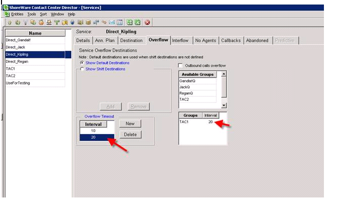
In figure One below, you can clearly see that we have a number of services defined, including a service named TAC1.   Let us assume that this is a technical service group and that TAC1 is comprised of Agents/technicians that include Agent Gandalf, Kipling, Regan and Jack.      You can also see that a service has been enabled by the name “Direct Kipling”.    This service was created to enable callers to Kipling’s DID number to be brought into the Contact Center, and routed to Kipling even though they did not enter through the TAC1 service.   Hopefully, we can now count the phone calls Agent Kipling is handling that otherwise would not be reportable!

ecc_figure_1

In Figure One we can also see that we have set an “Overflow” counter that,  should anyone be in the Kipling Queue for 10 seconds they will overflow to the TAC1 queue.  What is interesting is that when you overflow in the ShoreTel Contact Center,  you don’t leave the queue you are in, you basically add another queue containing agents that have a cumulative effect on the call.    Should that “overflow” not result in an available agent and the caller continues to wait for service, you can actually set a second timer that would “overflow” (e.g. expand the number of agents ) to yet another queue.

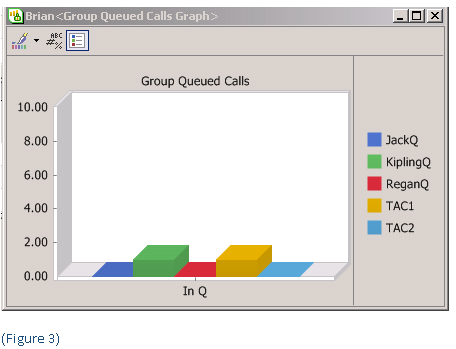
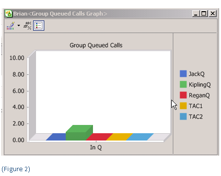
In Figure two, you can see the original call in the Queue for Kipling.  After the pre-configured overflow interval is met, the call is distributed to the “overflow” queue but is also available to the original queue.  You can see this in Figure Three, by noting that the call is now in queue in both the Kipling and TAC1 queue.   In this way, if an agent becomes available, in either the original queue or the “overflow” queue, the call will be answered.   Had we set up a second interval timer in the Service, we could expand the number of Agents to include the additional group specified by that timer.  This is one of the more interesting, if not misunderstood capabilities of the ShoreTel “overflow” concept!

ecc-figure-21ecc_figure-31

More on ShoreTel LLDP – follow up to previous blog post!

This is a follow up post to an earlier post on LLDP-MED. VoIP phones on the market today follow the same basic boot and operations process:

1 – Wait for an LLDP packet from the Ethernet switch

2- Send a DHCP discovery packet to find the DHCP Server

3- Send a DHCP request to the DHCP server to get an IP address

4- Send an LLDP-MED packet to the Ethernet switch

5- Wait for an LLDP-MED packet from the Ethernet switch and read the Network Policy TLV to get the VLAN ID, L2 priority and DSCP value

6 – Download applciations and software from the “call manager”

7 – After configuration , voice packets are sent as tagged frames and data packets are sent as untagged frames

The ShoreTel implementation of LLDP seems to follow this process only after step 5, the result of the IP Phone learning LLDP by having its firmware configured. In other words, a phone out of the box is a hung of iron with no inherent ability to define itself as an IP phone to an LLDP enabled ethernet switch. The ShoreTel phone will still require an intial boot in the native VLAN and then reboot in the voice vlan, where it will then download its firmware. The real value here, is that once this process is “learned” by the ShoreTel phone, should the phone restart for any reason in the future, it can start at step one above. LLDP in ShoreTel is a version 9.1 feature enhancement not available in earlier releases of ShoreTel.

update 2/15 see  article at Support.DrVoIP.com

Putty Telnet into ShoreGear SG50V/SG90V

We had a lot of requests for examples of telneting into the SG Voice switches, so we though we would do a quick video on that process. The V switch is a very different animal from the rest of the SG family. Basically, a small Linux server lives inside the switch and contains a Flash memory card to hold Automated Attendant and Voice Mail for users assigned to that “server”. There are some characteristics about the V switch that you should know and we have tried to summarize them below. One of the most important characteristics, is that a V switch MUST have a time source or bad things will happen!

The entire telnet process into this switch is different. You can find your way down to the subdirectory that contains the famous IPBXCTL security shell and run it using the normal command sequence. You will see the “telnet enabled” message, but you will pull you hair out before you can telnet into the V switch. To get inside the switch, you will need to use an SSH client like Putty. You will also need to log in as either the Admin or the Root users. The Admin gets you to a safe menu configuration option and you should have no problem configuring the switch. Remember, you have to have that NTS in your configuration! Log in as the root user however, gets you a more powerful set of trouble shooting command and enable you to back up the Flash card, and to some other debugs that you can not do from the admin user.

The video clip below walks you through the process. Here are some of the highlights we have discovered working with the V switch,

· Limited media stream capability.

· 1U Half Width Switch

· Voice Mail stored as 8-bit WAV files from G.711/G.729

· Switch can negotiate ADPCM but can Not proxy G.729

· Switch runs under Linux (not VxWorks)

· Voicemail Switch uses Qmail not SMTP and does not support SMDI

· SG90V supports 90 voice mail boxes

· 1GB Compact Flash stores about 1500 minutes or 15 minutes per user

· Full CF Card = “voice mailbox full” message

· Holds all Automated Attendant Messages?

· Store prompts for up to four languages

· At boot, requires connectivity to HQ server for configuration

· Once operational, does not need server connectivity for VM/AA

· V switch MUST have NTS SMTP and FTP resource

· Console port = Linux Shell STCLI is default

ShoreTel SIP Trunk Configuration Parameters for Level 3

Generally, we do not fill out forms given to us by Carriers.   Most Carrier forms use nomenclature that is “Marketing Speak” and not technically driven.   It seems we have 100 different ways to refer to a TDM with PRI signaling and only one of them means anything to an engineer.   There are a variety of new delivery methods being offered to clients for PRI service and it is important to understand exactly what type of circuit you are actually being given.    A PRI may in fact be a SIP trunk from a Softswitch, through a CISCO IAD with a TDM interface for your SGT1.   Not necessarily a bad thing (though you should expect problems with Fax service) but it is a hybrid circuit and not a traditional TDM T1 to a circuit switched central office.   We are always eager to assist the client by speaking with the carrier and having a dialog as to the exact nature of the circuit, but we steer clear of filling out the forms they expect their new customers to complete!

Recently, while planning the implementation of a ShoreTel IPBX with 230 SIP trunks, I  had the experience of pulling together answers to L3 request for configuration data.  With the help of  Rod Davis, Juan Rubio and Steve Weinstock we were able to respond.   To my surprise, this time there was not a single marketing expression in the document!   The questions were specifically engineering oriented and designed to understand the capabilities of the IPBX that the SIP trunk service was being ordered to support.    I though it would be interesting to share that information with our readers.  The IPBX is the ShoreTel and the assumption made in these answers is that the ShoreTel is being front-ended by an Ingate Separator.   Here are the SIP configuration questions and answers:

level31

How to set up Backup for ShoreTel VG50 and VG90 V siwtches!

Both models of the ShoreTel VG90 and VG50 are availabe in V switch configurations.   The V switch configuration enables you to provide local voice mail and autoamted attendant functionality to a smalll site economically.  Compared to the cost of adding a distributed voice mail server, the SG50V and SG90V are economically viable alaternatives that should be considered as you plan for resilency and site continuity during a WAN outage.

Due to the CF card capacity, daily backup of  voice mail and automated-attendnat is advised.  When automatic backup is enabled in the ShoreWare Director, it begins immediately after the server completes its daily house-keeping operations.  Automatic Backup Stores Voicemail, Auot Attendant Data and switch  log fiels to an FTP server.  After completion of the daily file-system cleanup taks, the switch begings automatic backup.  A time stamp is appended to the name of the files copied to the target server.

Automatic backup provides a source for the most recent days voice mail and the other data in the event of a system failue.  It is not intended to be an archive of voice messages or a sourc fo retrieving deleted voice mail.  The following silent film clip walks you through the process of setting up an FTP site and properly configuring the ShoreWare Director for V switch backup!

Switch Connectivity Diagnostic

Most ShoreTel System Administrators learn early on that the “Quick Look” link in the ShoreWare Director is your best friend! After all, telephony trouble indications are easy to spot: Green is good, Red is Bad and yellow means “something needs attention”. At the first report of a trouble indication, a System Administrator will bring up a browser and get to the log in screen of the Shoreware Director portal. Quick Look, Under the Maintenance section of the administrator portal, provides an immediate snapshot of what is going on in the system. If you see any RED at the HQ level, you can drill down and find the site and switch that might be the source of your problem.

What happens when you look and you see Green?All is good!Why am I getting user reports of inability to complete a phone call?The very best next step for you to take is to click on the Switch Connectivity link under the same Maintenance section as Quick Look.The switch connectivity screen will illustrate any connectivity issues between switches on the network. It is very possible that the HQ server “sees” all is well and reports Green, but individual switches served by DVM’s, for example, do not see each other.By pinpointing the intersection of switches that can not communicate with each other, you will generally find a network or default gateway issue that is causing your negative user reports!As useful as the Quick Look may be, the Switch Connectivity page is a more useful diagnostic for locating network based issues.

switch-connectivityFor more detailed information about a switch, place the mouse cursor over the connectivity cell in question and status information will be displayed in the status bar at the bottom of your browser!  Green is Still Good and indicates the Switch is communicating with the other switches in the system.  Yesllo indicates that the switch connectivity is unknown because it can not communicate with TMS and RED indicates a complete loss of communications with the server!

The missing ShoreTel Beep!

In both ShoreTel Release 8 and 9 there is a very interesting behavior that will ultimately bring a client call to your support center.   The behavior is most obvious in a multi-site deployment in which there is only one HQ server providing voice mail services.    A call to a user at a remote site is RNA (i.e. ring no answer) transferred to the voice mail system.   The call entered the system on a PRI at the remote site and is then transferred across an MPLS WAN to the HQ server.   The caller hears the greeting: “I am not here, at the beep please leave a message”.   The caller dutifully waits for the “beep”, but it never comes.  What happens to it?

The fact of the matter is the “beep” was in fact played, but the caller did not hear it.   This has to do with the use of the G729 Codec on Inter site calls in this scenario.   The G729 is distorted to the point that the caller can not hear the beep.   The distortion appears to only be related to the implementation of the G.729 codec on the virtual soft switch.  As a troubleshooting step, I used a different phone system and an IP phone that was set to only use G.729.  When we called the HQ virtual soft switch over a local PRI trunk where ULAW was being used from the PRI switch to the HQ server, we heard the voicemail beep without distortion (through the G.729 codec as implemented on a different PBX).  It is only distorted when the virtual soft switch is trying to do G.729.

Outlined below are two WAV files of the normal beep (ULAW) and the distorted beep (Softswitch G.729).  We have also attached a visual representation of the audio files.  The distortion is audibly and visibly clear.  Our thinking is the “beep” is to short and to high a frequency, but we are not developers!  Currently, the only known fix for this is to change the Codec to G711.  That fixes the issue, but it may have a negative impact on your WAN plan!  I am sure there is a fix in the works back at the ShoreTel Mother ship, but we have not seen it yet.

waveforms

Route Points, IRN’s and Media Streams!

Lately the subject of ShoreTel Route Points and IRN’s has been getting a lot of “mind share” from those working with them.   Two questions:  How many Route Points can a ShoreTel server support?  How many IRN’s can an ECC support?  How many DNIS numbers can a ShoreTel support.   Seems like a simple set of questions, but the answers are something like “herding cats”.    Route Points are used in a ShoreTel system to accomplish call routing and TAPI connectivity between the IPBX and the Enterprise Contact Center, for example.   Let us assume, for purpose of illustration, that you have a large call center and you want to track the effectiveness of your advertising campaigns.   You determine to do this by tracking DNIS numbers.  Each DNIS represents a different advertising campaign.  Recently, I came across a client who was creating a route point – IRN pair for each DNIS number.   Nothing particularly wrong with this, but using the DNIS map would have required only one Route Point if the DNIs was pointing to the same Group of Agents (e.g. Service) in the Contact Center.

The Contact Center, currently can only map one DNIS number per IRN.  It is my understanding that ShoreTel may be moving toward 1000-1500 DNIS numbers in future ECC releases.  So if you want to run report about DNIS you might have to look in two databases: (a) the ShoreTel MySQL CDR database on the IPBX; and (b) the C2G database on the ECC.  You will need to use the GUID if you want to tie the two databases together to get the DNIS and Agent Events and Wrap codes.   If you bring the DNIS into the IRN,  to enable DNIS reporting in the ECC, you can see the list of IRN’s could get very long and there is a  limit.

I suspect that DNIS has a limitation as well.  My thinking is that DNIS numbers would live in the various SG switches.  So the ultimate answer to how many DNIS numbers you can have may be memory constraint and  configuration specific (e.g. different for each configuration).    If you have any input on this, I would welcome it!   At the end of the day what we know is that you can create Route Points all day long in ShoreTel (though I have not attempted to find the real limit).  If the Route Points live on the ShoreTel server the real limitation is the 254 simultaneous media streams that a Microsoft Server can support.   If you point 12 PRI’s at one server and you have the potential of having 276 simultaneous phone calls, bad things are going to happen.   You need to spread your media stream over multiple servers.   In the contact center, you generally shape media streams (e.g. IVR ports) to 150 per server.

The “devil is in the details”.